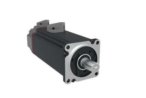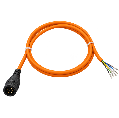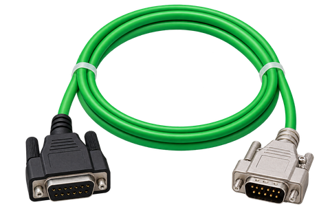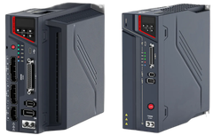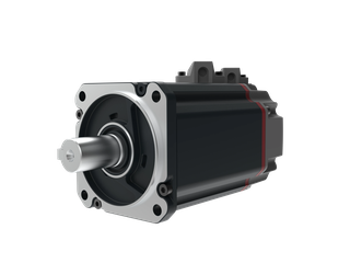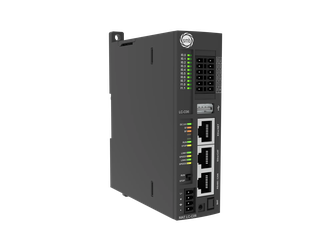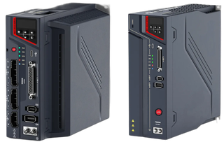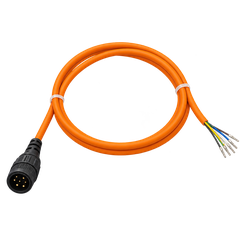

One set, controller to cable
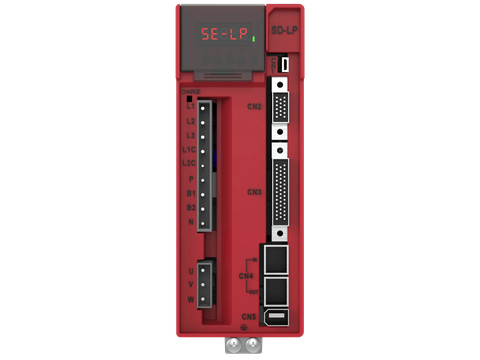
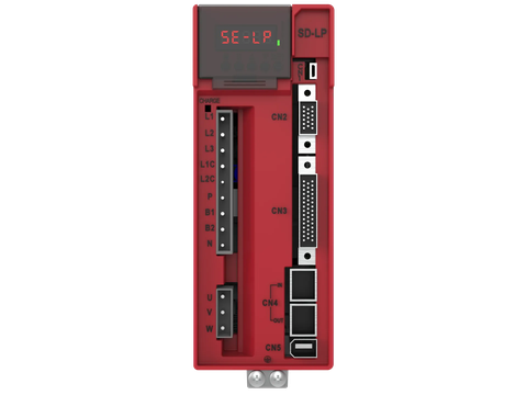
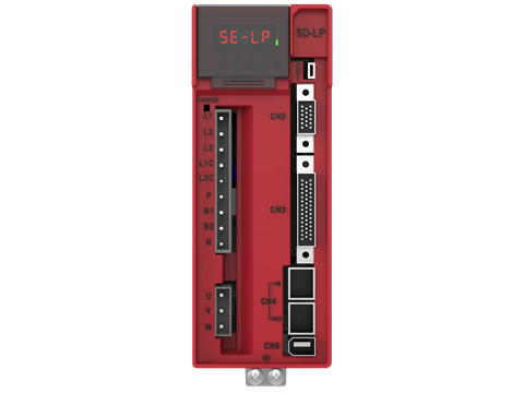
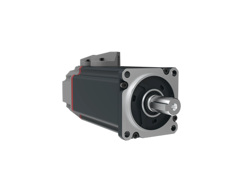
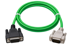
Controller, drive, motor, cable and connector arrive checked against each other; interface problems are solved at the desk, not on the shop floor.
Fast, repeatable pick-and-place and loading on X, Y and Z axes.
Cartesian robots and gantry systems do machine tending, pick-and-place, dosing, gluing and palletizing on linear axes. The mechanics are simple, programming is clear and the work envelope is large; success is the axes moving together, without jerk, to the same point every cycle.
On a long gantry two motors run as one axis.
Brake timing and STO hold the load safely.
S-curve profiles calm the gripper.
Controller, drive, motor, cable and connector arrive checked against each other; interface problems are solved at the desk, not on the shop floor.
EtherCAT, CANopen, Modbus RTU, CODESYS and CiA 402: your machine is not tied to a closed ecosystem.
The same team from sizing to commissioning, on site and remotely.
Manuals, CAD, ESI/EDS and firmware in the Document Centre; every product you choose comes with its documents.
How the machine is driven and the SMB products we choose for it.
Cartesian robots and gantry systems do machine tending, pick-and-place, dosing, gluing and palletizing on linear axes. The mechanics are simple, programming is clear and the work envelope is large; success is the axes moving together, without jerk, to the same point every cycle.
A gantry is measured by how fast and how calmly its axes settle.
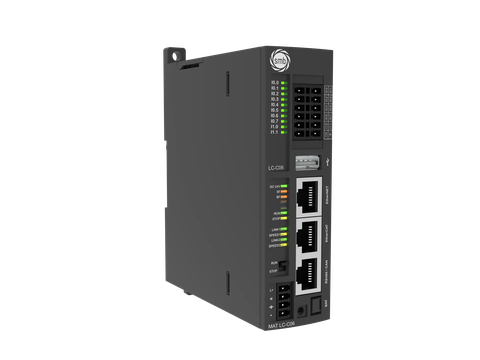
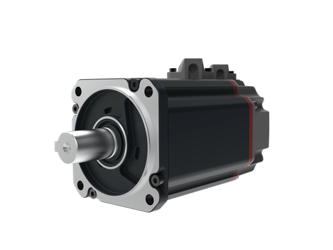
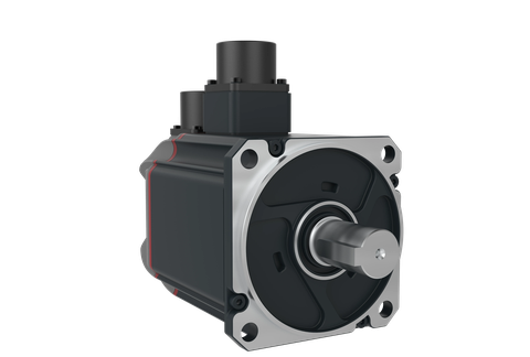
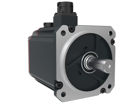
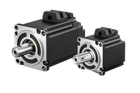
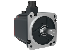
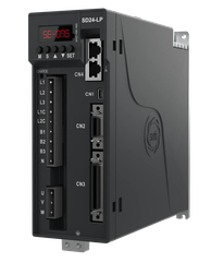
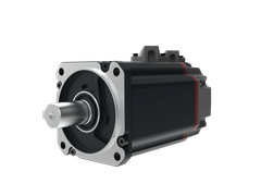
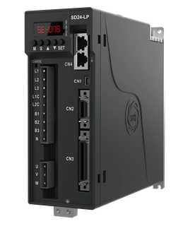
The X and Y axes are driven over EtherCAT by SD24-LP drives, or SDU3 on large gantries, with SM08–SM13 motors; the vertical Z axis uses a braked motor. A MAT-LC CPU runs interpolated motion and the sequence with PLCopen blocks in CODESYS.
We need the moving mass, strokes, speed and acceleration, cycle time and the transmission (belt, ball screw, rack). The sizer confirms each axis.
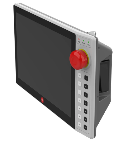
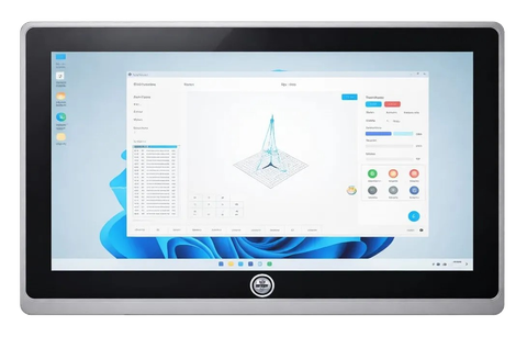
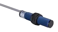
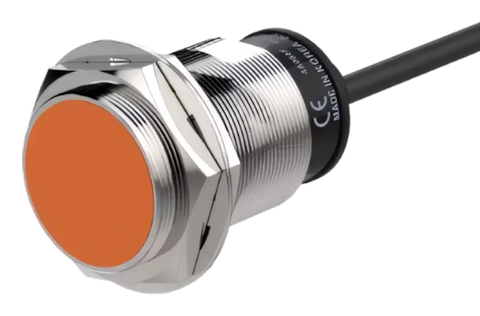
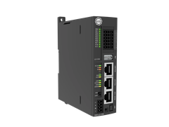
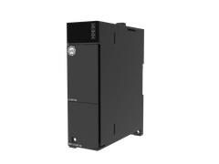
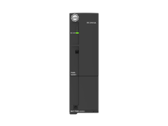
The boxes show the real products; click one to open the series.
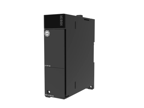 MAT-LC-DIT-08
PLC Digital Input Module — 8 × 24 V DC
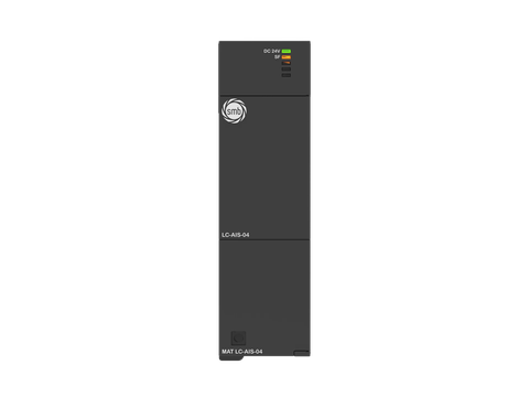 MAT-LC-DIT-16
PLC Digital Input Module — 16 × 24 V DC
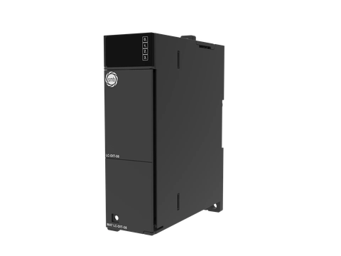 MAT-LC-AIS-04
PLC Analog Input Module — 4AI × 12-bit
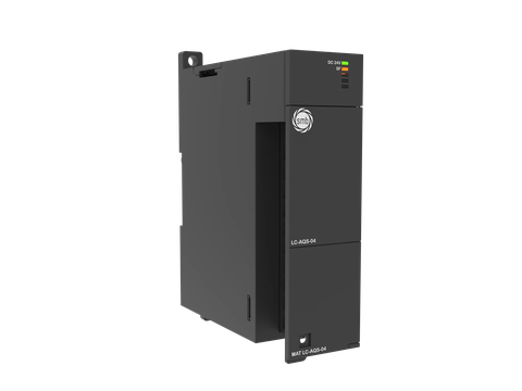 MAT-LC-AQS-04
PLC Analog Output Module — 4AQ × 12-bit
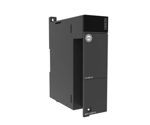 MAT-LC-DQT-16
PLC Digital Output Module — 16 × 24 V DC
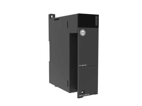 MAT-LC-DQT-08
PLC Digital Output Module — 8 × 24 V DC
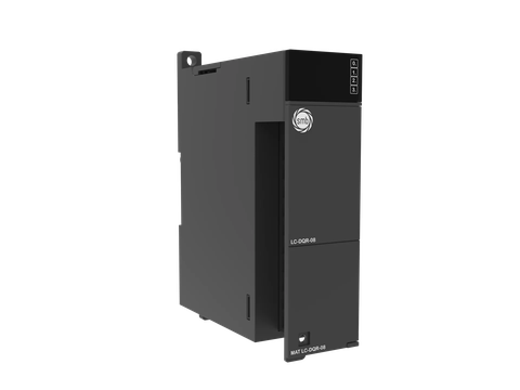 MAT-LC-DQR-16
PLC Digital Output Module — 16 × Relay
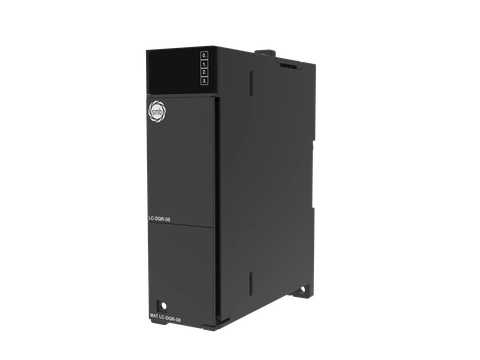 MAT-LC-DQR-08
PLC Digital Output Module — 8 × Relay
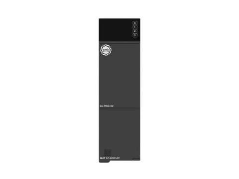 MAT-LC-HSC-02
Programmable Logic Controller Module High Speed Counter 2 x Differential/Single-Ended
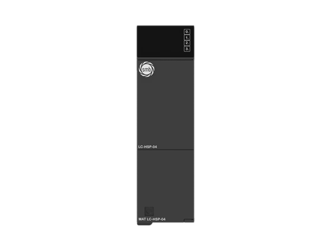 MAT-LC-HSP-04
Programmable Logic Controller Module High Speed Pulse 4 x Differential/Single-Ended
The industrial switch distributes Ethernet traffic between the controller, the operator panel and the engineering PC. It is part of the architecture, not part of the SMB catalogue.
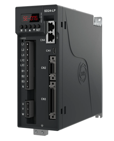 SD24-LP-04-D1-E
SD24-LP 400 W Single/Three-Phase 220 V AC EtherCAT Servo Drive
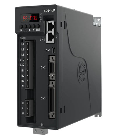 SD24-LP-07-D1-E
SD24-LP 750 W Single/Three-Phase 220 V AC EtherCAT Servo Drive
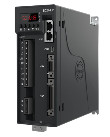 SD24-LP-10-D1-E
SD24-LP 1 kW Single/Three-Phase 220 V AC EtherCAT Servo Drive
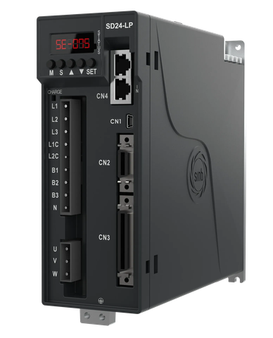 SD24-LP-15-D1-E
SD24-LP 1.5 kW Single/Three-Phase 220 V AC EtherCAT Servo Drive
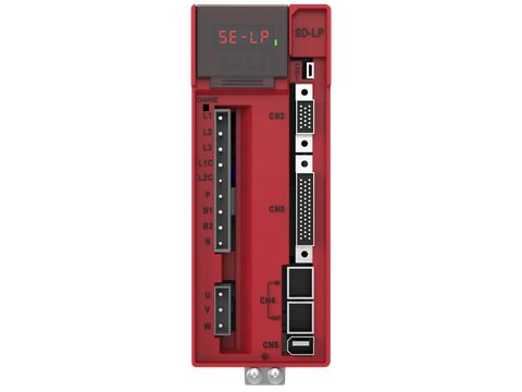 SD-LP-04-D1-E
SD-LP 400 W Single/Three-Phase 220 V AC EtherCAT Servo Drive
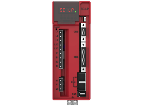 SD-LP-07-D1-E
SD-LP 750 W Single/Three-Phase 220 V AC EtherCAT Servo Drive
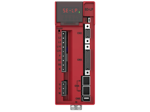 SD-LP-10-D1-E
SD-LP 1 kW Single/Three-Phase 220 V AC EtherCAT Servo Drive
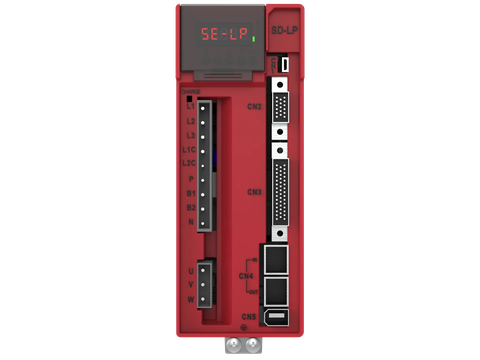 SD-LP-15-D1-E
SD-LP 1.5 kW Single/Three-Phase 220 V AC EtherCAT Servo Drive
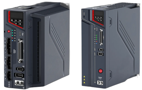 MAT-SDU3-MP-300-D3-E
SDU3 Series 3 kW Three-Phase 380 V AC EtherCAT Servo Drive
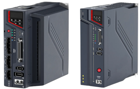 MAT-SDU3-MP-500-D3-E
SDU3 Series 5 kW Three-Phase 380 V AC EtherCAT Servo Drive
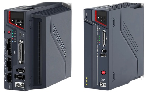 MAT-SDU3-MP-750-D3-E
SDU3 Series 7.5 kW Three-Phase 380 V AC EtherCAT Servo Drive
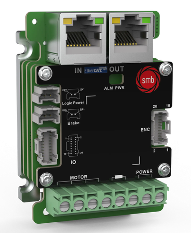 MAT-SDE3-LV-7020-NC-E
SDE3 Series 750 W EtherCAT Servo Drive — Open-frame
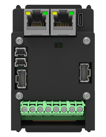 MAT-SDE3-LV-7020-CS-E
SDE3 Series 750 W EtherCAT Servo Drive — Enclosed
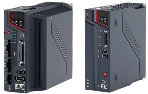 MAT-SDU3-MP-040-D3-E
SDU3 Series 400 W Three-Phase 380 V AC EtherCAT Servo Drive
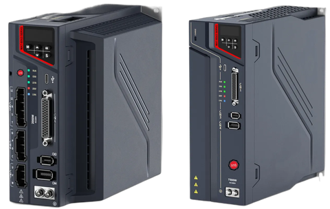 MAT-SDU3-MP-075-D3-E
SDU3 Series 750 W Three-Phase 380 V AC EtherCAT Servo Drive
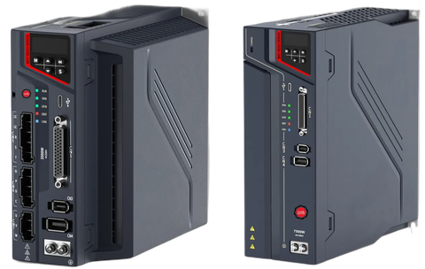 MAT-SDU3-MP-100-D3-E
SDU3 Series 1 kW Three-Phase 380 V AC EtherCAT Servo Drive
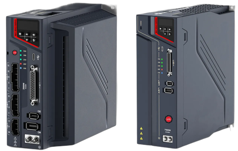 MAT-SDU3-MP-150-D3-E
SDU3 Series 1.5 kW Three-Phase 380 V AC EtherCAT Servo Drive
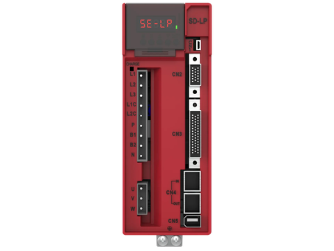 SD-LP-04-D1-C
SD-LP 400 W Single/Three-Phase 220 V AC CANopen Servo Drive
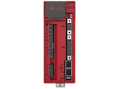 SD-LP-07-D1-C
SD-LP 750 W Single/Three-Phase 220 V AC CANopen Servo Drive
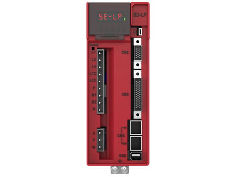 SD-LP-10-D1-C
SD-LP 1 kW Single/Three-Phase 220 V AC CANopen Servo Drive
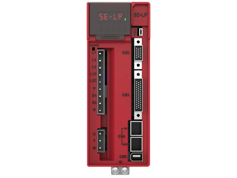 SD-LP-15-D1-C
SD-LP 1.5 kW Single/Three-Phase 220 V AC CANopen Servo Drive
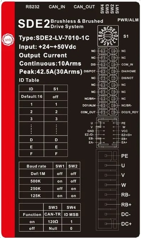 MAT-SDE2-LV-7010-CS-C
SDE2 Series 400 W CANopen Servo Drive — Enclosed
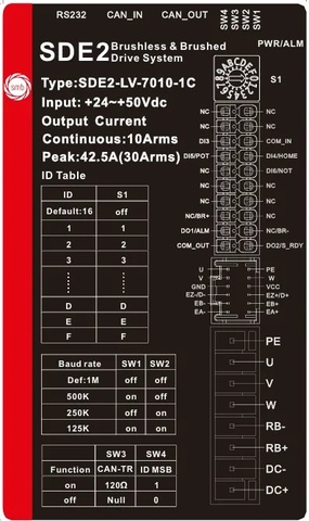 MAT-SD2E2-LV-7030-CS-C
SD2E2 Series 2 × 1.2 kW Dual-axis CANopen Servo Drive — Enclosed
SMB controllers are programmed in CODESYS: the IEC 61131-3 languages, integrated motion and a single project covering both machine logic and the axes.
PLCopen Motion Control function blocks give every axis the same standard interface, so proven machine code carries over from one project to the next.
SMB servo drives implement the CiA 402 drive profile: the same state machine and the same operating modes over EtherCAT and over CANopen.
Each axis, its task, its control mode and the drive–motor pair on it.
CSP · EtherCAT
CSP · EtherCAT
CSP · EtherCAT
CSP: cyclic synchronous position · CSV: cyclic synchronous velocity · CST: cyclic synchronous torque · PP: profile position. The series is confirmed by load and supply voltage.
From requirement to support; the SMB products and tools each step uses.
The motion profile, load and cycle time of every axis are collected; torque, speed and inertia ratio are calculated per axis.
The network (EtherCAT, CANopen, Modbus RTU), the controller and the drive–motor pair per axis are chosen; the safety and power side is drawn at this step.
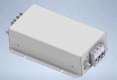
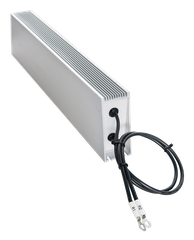
Power and encoder cables run in separate ducts with their shields bonded 360°; an EMI filter goes at the drive input and a braking resistor where the load regenerates.
In the CODESYS project the axes are defined with PLCopen blocks; the drives join the network through their ESI/EDS files and run the CiA 402 state machine.
After wiring and direction checks the gains are tuned and the axes homed; the operator panel carries the machine recipes.
Alarm codes, spare parts, firmware and training, from the same engineering team.
Hardware, software, engineering and lifecycle.
Controller, servo drive, motor, cable and connector: one set, checked to work together.
The CODESYS project, PLCopen motion blocks and know-how specific to this machine.
Sizing, architecture, commissioning and tuning, on site and remotely.
Manuals, ESI/EDS files, spare parts and training.
The topics engineers in this industry ask about most, each with answers, checklists and troubleshooting steps.